Pt100 temperature sensor is a common type of temperature sensor used in various types of measurement and control. The Pt100 sensor itself is the measuring element of the actual temperature sensor, which, in addition to the resistor, normally consists of the connecting wires (drain and drain cable) and external terminals for connecting electrical measuring instruments, as well as external components such as a shield, connection head or connection cable. In industry, the most commonly used temperature sensor is the Pt100. Among all industrial temperature measurements, more than 70% are handled precisely by resistance temperature sensors built on the basis of the Pt100 sensor. Why? Primarily because of their wide measuring range, the linearity of their measuring characteristics, their durability, accuracy and, last but not least, their ease of connection.
Resistive temperature sensors work by measuring the change in electrical resistance of the metal as the temperature changes. By measuring these changes, it is possible to determine the temperature value.
The Pt100 temperature sensor is a commonly used type of temperature sensor in various types of measurement and control. The platinum Pt100 sensor itself is the measuring element of the actual temperature sensor, which, in addition to the resistor, comprises, as a standard, the connecting cables (supply and drain cable) and external terminals for connecting electrical measuring instruments, as well as external components such as the sheath, connection head or connection cable. In industry, the most commonly used temperature sensor is the Pt100.
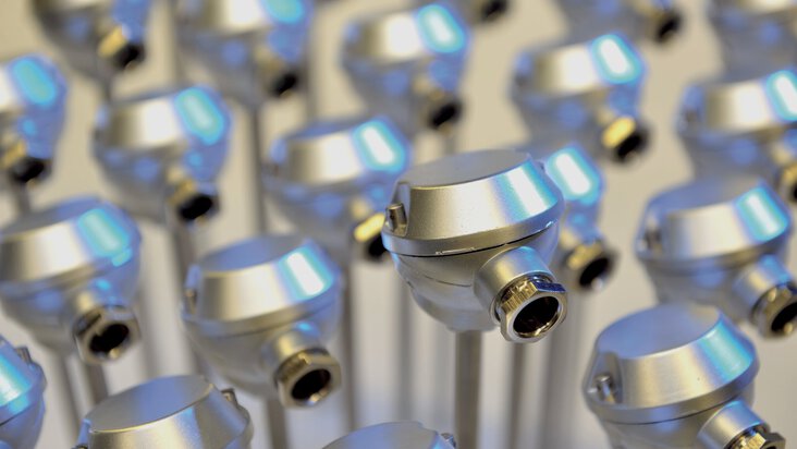
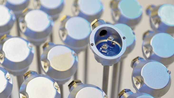
Pt100 sensor as part of a resistance thermometer
Among all industrial temperature measurements, more than 70% are handled precisely by Pt100 resistance temperature sensors. Why are these temperature sensors used so widely? Primarily because of their wide measuring range, the linearity of their measuring characteristics, their durability, their accuracy and, finally, their ease of connection.
Although the term Pt100 specifically refers to the temperature sensor itself, it is often used as a synonym for a resistance temperature sensor when combined with the term "sensor." Other commonly accepted names for resistance temperature sensors include RTD sensor (from English: Resistance Temperature Device), resistance thermometer (industrial thermometer), resistive sensor, resistance temperature sensor, Pt100 thermometer, or resistive thermometer.
The Pt100 temperature sensor is used for measuring the temperature of:
We distinguish the following types of temperature sensors:
Are you looking for Pt100 resistance temperature sensors? Great! We have an exceptional offer of various types and purposes of resistance temperature sensors for you. JUMO Pt100 temperature sensors have been successfully used in almost all industrial sectors for many years. This is mainly due to the versatility and wide range of possibilities for producing highly specified versions of our RTD temperature sensors, as well as our reliable standard versions of resistance thermometers available in various variants, such as screw-in sensors, plug-in sensors, or resistive sensors with a connection cable.
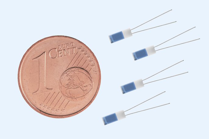
Do you need only platinum Pt100 temperature sensors? You've come to the right place! JUMO platinum Pt100 temperature sensors are manufactured using the most advanced thin-film technology. This ensures excellent accuracy and long-term measurement stability of our sensors. What distinguishes JUMO platinum temperature sensors is the wide temperature range (from -70°C to 600°C), the availability of many different models, and various resistance values.
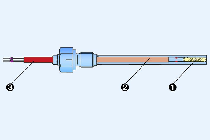
Structure of an RTD: 1 = sensor, 2 = inner line, 3 = connection line
The connection head contains a connection socket for attaching the connection cable. The thermometer is fixed by a flange. Thermometers of this type allow measurement of up to 600 °C and are frequently used in furnace construction.
Screw-in thermometers allow the pressure-tight termination of the process. In the case of thermometers with connecting cable, the maximum temperature is limited by the cable. Maximum temperatures of about 400 °C can be measured.
Surface probes have the advantage that they do not require a process connection. They measure the temperature of a surface and thus allow conclusions to be drawn about the medium temperature in a pipe system or tank. However, precision measurements are not possible with them.

Insertion thermometer with connection head
In order to allow easy mounting/dismounting of screw-in thermometers, it is often useful to obtain them with a connector plug. The connection systems shown below are frequently used.

Machine connector M12 × 1 4-pole according to IEC 60947-5-2

Connector according to DIN EN 175301
As far as the resistance thermometers have been equipped with a platinum sensor (like Pt100 or Pt1000), they are compatible. Thanks to the DIN EN 60751 standard, a replacement thermometer will have the same output signal.
Resistance thermometers can be connected via a two-wire, three-wire or four-wire connection.
In the simplest case, an RTD can be connected via two wires. However, the two-wire connection results in a so-called line offset. For every 0.38 Ω of lead resistance, a Pt100 indicates a temperature that is 1 Kelvin too high. With the same ratios, an offset of 0.1 Kelvin occurs with a Pt1000. Even with relatively short cable lengths, the deviation in the display will be so great that a temperature adjustment must be made in the evaluation unit. This creates unnecessary effort, therefore resistance thermometers should preferably be connected in three- or four-wire technology.
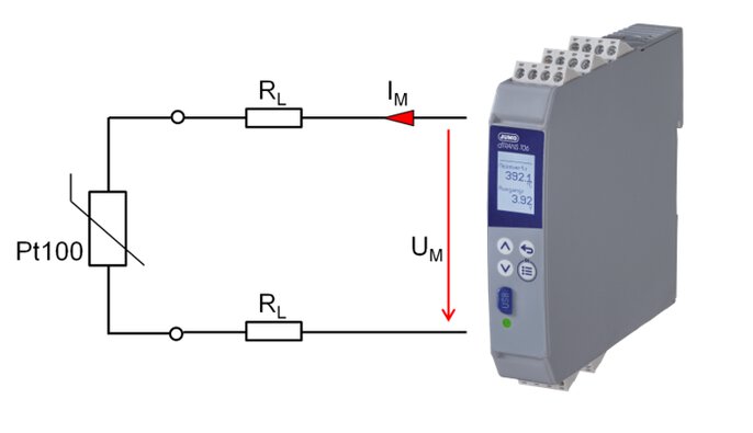
Field device with two-wire connection
With the three-wire connection, an additional wire connects the resistance sensor to the evaluation unit. The evaluation unit measures the voltage drop at the resistance sensor and the connecting leads (UM). With the help of the third conductor, the evaluation unit further determines the voltage drop at one conductor (UL½ ). The double amount of this voltage is subtracted from UM and thus the voltage drop at the resistance sensor is determined. If all wires have the same resistance, no error results from the line resistances and the resistance of the sensor is determined without error. The three-wire connection is sufficient for most applications.
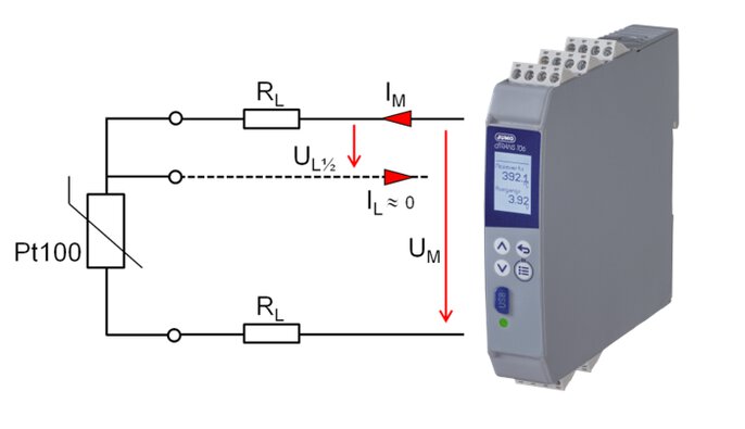
Field device with three-wire connection
The fourth wire is used to determine the exact voltage at the resistance sensor in the four-wire connection.
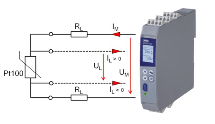
Field device with four-wire connection
In this way, the resistance value is always determined accurately - even if the wire or terminal resistances are different. It is used for high accuracy requirements such as in reference or resistance thermometers in the laboratory field.
The platinum sensors in the resistance thermometers have only a low drift behavior, i.e. their output signal changes only slightly over time. Nevertheless, calibration should be carried out regularly to check whether the temperature is still being measured with the required accuracy. Finally, regular calibration ensures high product quality. If a plant operator works according to guidelines and standards such as ISO 9001:2008, ISO 14001:2004 + Cor1:2009, he is even obliged to calibrate the measuring chains.
If the resistance thermometers are operated via three or four conductors, it is irrelevant whether it is a Pt100 or Pt1000 sensor. The Pt1000 only has an advantage when used in two-wire technology, because with it the lead offset is only 1/10 of the Pt100. Example: The lead resistance of a connection line is 1.9 Ω. When using a Pt100, a line offset of approx. 5 Kelvin occurs - a line compensation must be carried out. If a Pt1000 is used, the offset is 0.5 Kelvin - in many applications, an adjustment is not necessary.